Rewriting the video stream from a wi-fi borescope camera
Updated July 18, 2021 - Thanks to Michael Karr the video corruption can now be completely removed.
Introduction
I purchased a cheap wi-fi borescope camera (the Depstech WF028 Yellow) so I could examine the ductwork in my house. The manufacturer supplies mobile apps (DEPSTECH on iOS, for example) for controlling settings and viewing video and explicitly does not support using the device from desktop operating systems. Although the mobile apps do work, they receive lukewarm reviews and look kind of seedy.
I bypassed those apps and successfully obtained usable, low-latency video output that can be viewed and processed with standards-based tools.
Prior work
Nathan Henrie reverse engineered a similar wi-fi borescope. His four posts provided an excellent starting point for my efforts.
- In part 1, he connects to the device’s serial debug port and views boot log output.
- In part 2, he dumps the flash module and makes the flash dump available.
- In part 3, he decodes the device’s UDP command/response protocol and creates a shell script that can send commands to the device.
- In part 4,
he identifies the video protocol in use and streams video using standard
tools. He identifies the following command, which allows video to be viewed
directly in VLC:
$ vlc 'tcp://192.168.10.123:7060/stream.mjpeg'
Limitations of prior work
Artifacts appear in the video stream that make VLC freak out and re-buffer, causing choppiness and latency that make the video stream almost unusable. Using VLC to view the video stream is a far poorer user experience than using the supplied mobile app.
Video stream analysis
Preliminary hex dump
I turned the device’s camera light off, put my finger over the front of the camera, and used netcat to dump video from the device for a few seconds.
$ nc 192.168.10.123 7060 >vidblack.log
The start of the stream looks curious:
$ hexdump -C vidblack.log |head -1
00000000  42 6f 75 6e 64 61 72 79  53 00 00 01 00 dc 4e 00  |BoundaryS.....N.|
The dump starts with the string BoundaryS, which is certainly not part of any
standard video protocol. However, the 010
Editor’s JPG template confirms that
the stream contains a JPEG image prepended with 41 bytes of garbage.
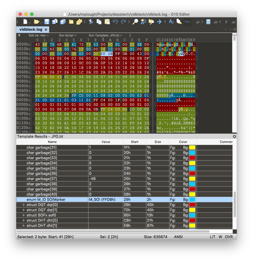
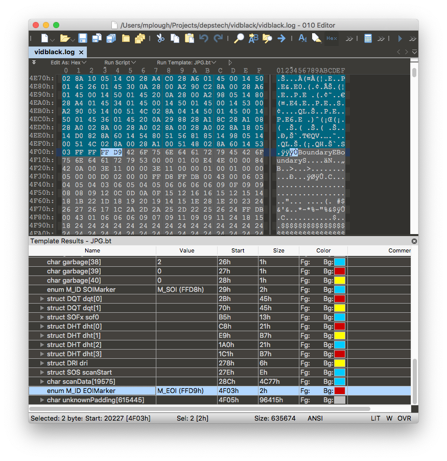
The string BoundaryE immediately follows the EOI marker, which is immediately
followed by BoundaryS again.
Corroboration via executable analysis
Previously, I described a procedure for making two interesting binaries
available for more detailed analysis.
I used the Retargetable Decompiler (GitHub
repo) to examine these two files, app_cam
and app_detect.
$ retdec-decompiler.py /path/to/app_cam --cleanup -k
$ retdec-decompiler.py /path/to/app_detect --cleanup -k
The -k option keeps unreachable functions in the C output and the
--cleanup option keeps things tidy. Four files result from running these two
commands, app_cam.c, app_detect.c, app_cam.dsm, and app_detect.dsm.
The decompiled C files aren’t perfect or complete but they are a nice place to
start. The disassembly is always available for more detailed analysis.
The app_cam.c file contains a very interesting function,
video_set_headtail:
int32_t video_set_headtail(int32_t a1, int32_t a2, int32_t a3, int32_t a4, int32_t a5, uint32_t a6, uint32_t a7, uint32_t a8, uint32_t a9, uint32_t a10, uint32_t a11, uint32_t a12, uint32_t a13) {
    // 0x413830
    g1 = a1;
    int32_t v1 = g1; // 0x413848
    *(char *)v1 = 66;
    *(char *)(v1 + 1) = 111;
    *(char *)(v1 + 2) = 117;
    *(char *)(v1 + 3) = 110;
    *(char *)(v1 + 4) = 100;
    *(char *)(v1 + 5) = 97;
    *(char *)(v1 + 6) = 114;
    *(char *)(v1 + 7) = 121;
    *(char *)(v1 + 8) = 83;
    *(char *)(v1 + 9) = (char)a2;
    *(char *)(v1 + 10) = (char)a3;
    *(char *)(v1 + 11) = (char)a4;
    *(char *)(v1 + 12) = (char)a5;
    *(char *)(v1 + 13) = (char)a6;
    *(char *)(v1 + 14) = (char)(a6 / 256);
    *(char *)(v1 + 15) = (char)(a6 / 0x10000);
    *(char *)(v1 + 16) = (char)(a6 / 0x1000000);
    *(char *)(v1 + 17) = (char)a7;
    *(char *)(v1 + 18) = (char)(a7 / 256);
    *(char *)(v1 + 19) = (char)(a7 / 0x10000);
    *(char *)(v1 + 20) = (char)(a7 / 0x1000000);
    *(char *)(v1 + 21) = (char)a8;
    *(char *)(v1 + 22) = (char)(a8 / 256);
    *(char *)(v1 + 23) = (char)(a8 / 0x10000);
    *(char *)(v1 + 24) = (char)(a8 / 0x1000000);
    *(char *)(v1 + 25) = (char)a9;
    *(char *)(v1 + 26) = (char)(a9 / 256);
    *(char *)(v1 + 27) = (char)(a9 / 0x10000);
    *(char *)(v1 + 28) = (char)(a9 / 0x1000000);
    *(char *)(v1 + 29) = (char)a10;
    *(char *)(v1 + 30) = (char)(a10 / 256);
    *(char *)(v1 + 31) = (char)a11;
    *(char *)(v1 + 32) = (char)(a11 / 256);
    *(char *)(v1 + 33) = (char)a12;
    *(char *)(v1 + 34) = (char)(a12 / 256);
    *(char *)(v1 + 35) = (char)(a12 / 0x10000);
    *(char *)(v1 + 36) = (char)(a12 / 0x1000000);
    *(char *)(v1 + 37) = (char)a13;
    *(char *)(v1 + 38) = (char)(a13 / 256);
    *(char *)(v1 + 39) = (char)(a13 / 0x10000);
    g1 = v1;
    *(char *)(v1 + 40) = (char)(a13 / 0x1000000);
    int32_t v2 = v1 + a6; // 0x413b84
    *(char *)(v2 + 41) = 66;
    *(char *)(v2 + 42) = 111;
    *(char *)(v2 + 43) = 117;
    *(char *)(v2 + 44) = 110;
    *(char *)(v2 + 45) = 100;
    *(char *)(v2 + 46) = 97;
    *(char *)(v2 + 47) = 114;
    *(char *)(v2 + 48) = 121;
    *(char *)(v2 + 49) = 69;
    return 69;
}
The pointer arithmetic done on v1 shows that the video header
is always 41 bytes long and contains a constant string followed by a series of
values in little-endian byte order. The pointer arithmetic done on v2 shows
that the trailer contains a constant string and is always 9 bytes long.
Translating the integers to ASCII characters and rewriting snippets of this
function makes things slightly clearer:
*(char *)v1 = 'B';
*(char *)(v1 + 1) = 'o';
*(char *)(v1 + 2) = 'u';
*(char *)(v1 + 3) = 'n';
*(char *)(v1 + 4) = 'd';
*(char *)(v1 + 5) = 'a';
*(char *)(v1 + 6) = 'r';
*(char *)(v1 + 7) = 'y';
*(char *)(v1 + 8) = 'S';
...
*(char *)(v2 + 41) = 'B';
*(char *)(v2 + 42) = 'o';
*(char *)(v2 + 43) = 'u';
*(char *)(v2 + 44) = 'n';
*(char *)(v2 + 45) = 'd';
*(char *)(v2 + 46) = 'a';
*(char *)(v2 + 47) = 'r';
*(char *)(v2 + 48) = 'y';
*(char *)(v2 + 49) = 'E';
That’s good enough – there is no reason to dive into assembly code for purposes of understanding the video stream format.
Interpreting the header
Rather than going through the video stream by hand and extracting frame headers, I used the Ragel regular language parser generator to create a tool that would do so automatically.
The stream language is as follows:
begin = ('BoundaryS');
end = ('BoundaryE');
header = (
    any{4}
    image_size
    any{4}
    frame_number
    any{4}
    any{4}
    any{4}
    any{4}
)
jpeg = (any* -- end);
main := (begin header jpeg end)*;
It is unlikely that the stream BoundaryE will occur within the JPEG image
data. If it does, the video output is already pretty corrupt, so this really
won’t make things much worse.
Interpreting the JPEG frame contents
I used the 010 Editor to extract the first frame by hand. According to
mediainfo, it’s a 1280x720 JPEG image encoded in the YUV color space with
4:2:2 chroma subsampling. Not much of a surprise.
It is more surprising that the frame contains a DRI (Define Restart Interval) marker.
FF DD 00 04 00 50
The last two bytes in this marker tell us that the image will contain an RSTn (Resync) marker every 80 image blocks called minimum coded units (MCUs). See the JPEG File Layout and Format for further (terse) explanation of JPEG marker types, and see ImpulseAdventure for an excellent explanation of MCUs.
Restart markers allow resynchronization after an error, so it should be possible to mitigate the stream corruption – especially since things look pretty much fine in the mobile app.
Image decoding failure with libavcodec
Both VLC and ffmpeg use libavcodec under the hood so both tools will present similar viewing issues.
Viewing issues can be reproduced on the first frame, which I previously extracted. Using ffmpeg to convert the frame to JPEG gives a half-green image when the whole thing should be black. This command results in the following image:
$ ffmpeg -loglevel warning -i frame1.log 1.jpg
[mjpeg @ 0x7f98ba003400] mjpeg_decode_dc: bad vlc: 0:0 (0x7f98ba002448)
[mjpeg @ 0x7f98ba003400] error dc
[mjpeg @ 0x7f98ba003400] error y=43 x=78

The ffmpeg run’s output on stdout says that a bad variable-length code was encountered while attempting to decode the direct current (DC) term of a discrete cosine transform. The error occurred in MCU (78, 43).
A brief aside: mcutool
Since very few tools display information about the size and number of minimum coded units in JPEG images, I wrote mcutool, an extension of a shell script on quippe.eu, to extract that information from the images produced by the borescope.
Running the tool on the frame under examination yields the following output:
$ mcutool.sh frame1.log
width	1280
height	720
mcu_x	16
mcu_y	8
n_full_mcu_x	80
n_full_mcu_y	90
n_mcu_x	80
n_mcu_y	90
n_mcus	7200
The image is 80 MCUs wide and 90 MCUs tall, so it’s remarkable that libavcodec fails to decode the whole bottom half of the image after an error is encountered.
Analysis of libavcodec’s mjpeg decoder
To understand what’s happening, I cloned the ffmpeg Git repository listed on the
download page and dug into
libavcodec/mjpegdec.c. I did not run a debugger as I did not want to compile
from source.
Line numbers discussed are as of commit
e3dddf2142e21354bbeb27809e7699900a19ee0c made on December 7, 2019.
The error output mjpeg_decode_dc: bad vlc: 0:0 is printed from
mjpeg_decode_dc on line 773. At that point, the call stack must be as
follows, with the most recent call listed last:
ff_mjpeg_decode_frame(line 2322, called via function pointer on line 2368)ff_mjpeg_decode_sos(line 1616, called on line 2537)mjpeg_decode_scan(line 1408, called on line 1765)decode_block(line 791, called on line 1484)mjpeg_decode_dc(line 773, called on line 797)
On line 2378 within ff_mjpeg_decode_frame, the library notes restart markers
when it sees them:
        if (start_code >= RST0 && start_code <= RST7) {
            av_log(avctx, AV_LOG_DEBUG,
                   "restart marker: %d\n", start_code & 0x0f);
            /* APP fields */
        }
However, it doesn’t do anything about them. The switch block in that same
function does not respond to restart markers so ff_mjpeg_decode_sos must
decode the whole image in one pass.
In short, decoding is not resumed at the next restart marker if an error is encountered. In the future, it may be beneficial to add error recovery behavior to the decoder.
Fixing the stream
While adding error recovery to libavcodec’s JPEG decoder will be the most complete and authoritative fix to the issue, I don’t feel like doing that right now. Let’s be honest, I’m doing this for fun, and compiling ffmpeg from source doesn’t sound appealing right now.
There is another way. The jpegtran program accepts JPEG input on stdin, transforms it, and writes a new JPEG to stdout. The tool uses restart markers correctly when decoding an image, so the output is far more reasonable:
$ <frame1.log jpegtran 1_better.jpg
The jpegtran re-encode takes about 15-30 milliseconds seconds per sample
frame from the camera. Since the borescope camera runs at about 7 frames per
second, this is plenty fast enough to process each frame of video in real time.
I updated my Ragel tool to rewrite each frame by forking a jpegtran
subprocess, piping the bad frame in, reading in the re-encoded jpeg, and then
writing the re-encoded jpeg to stdout. The tool can then be used in a
pipeline.
The following pipeline acquires video from the camera, logs the raw stream to a
file for later playback, rewrites the stream in real time, and displays video.
A named pipe is used because ffplay only reads files and does not accept
input on stdin.
mkfifo vid.fifo
nc 192.168.10.123 7060 \
    | tee v.log \
    | borescope_stream --rewrite-jpeg >vid.fifo & \
    ffplay -hide_banner -loglevel error -f mjpeg vid.fifo
It uses about 50% CPU on a mid-2012 i7 MacBook Pro.
Source code for the borescope_stream program is available on
GitHub.
Update - July 18, 2021 Source code from the original time of writing is available at commit 2f7626e0e4240c9456dcadf2d94c490894d19442.
Results
Output latency is low and consistent.
In a sample capture of 1000 frames, jpegtran found that 60% of them contained
corrupt data. However, even frames that jpegtran does not flag as corrupt
generally contained a significant banding artifact about halfway down the
height of the image.
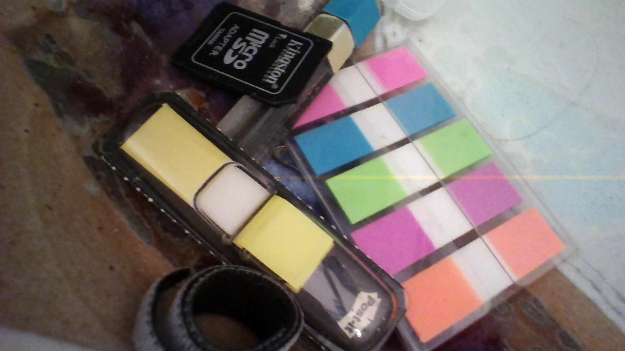
Visual artifacts don’t show up in the DEPSTECH mobile app. It’s not clear what is different about the decoder used in the mobile app or if some form of stream obfuscation is performed.
Future work
Multiple Android apps exist to read data from these wi-fi borescope cameras. For example:
- F100 1.8 -
com.tony.molink.zcf100 - Mo-View -
com.tony.molink.moview_28.apk - DEPSTECH-WiFi 3.7 -
com.tony.molink.tonseecamview-v3.7.apk - USB CAMERA 2.4 -
com.tony.usbcamera.molink-v2.4.apk
The DEPSTECH-Wifi app appears to be packed/encrypted using Jiagu and Qihoo. Analysis won’t be straightforward but it may yield information about differences in JPEG decoding.
Update - July 18, 2021
In June 2020, Michael Karr figured out the corruption in the video stream and wrote a tool to remove the corruption from the video stream. It was amazing to be able to build on Nathan Henrie’s work and then to see Michael Karr build upon my own. Michael did what I couldn’t do; he finally solved this puzzle.
I have updated the borescope_stream application to remove the corruption
as described in Michael Karr’s writeup. There is no longer a need to involve
the jpegtran application. Updated source code is available on
GitHub.